1. Active region:
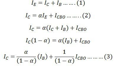
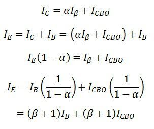
In this region the transistors act as an amplifier Ic = β* I b
2. Cut-off region:
In this region, the transistors act in a sleepy mode which means the transistor Turns off. The current through the collector is in the terminal is 0
3. Saturation region:
In this region, the transistors act in fully active mode. which means the transistor work on fully turned on mode.
we will discuss the regions in another article.
The BJT transistors are working as current controlling devices. The current flow is proportional to the voltage applied across the base terminal. The small current input to the base terminal controls the much larger current flowing through the collector. The current flow direction of this BJT transistor is from emitter to collector which is right opposite direction to the electrons flow. The BJT transistor has two types PNP and NPN transistors both of these transistors are working on the same function the only difference is their polarity is different from one another.
Bipolar Transistor has three-terminal, Each of those terminals connected in a different way by making the terminal common to other input and output terminals. Each of the Transistors statistics characters differ from that of another. These are the following configuration methods that is considered on BJT
It has voltage gain but doesn't have a current gain
- check here my previous tutorials
- ESP32-CAM Face detection|Face Recognition
- Machine to Machine Interactions
- mesh networking- explained
Common Base configuration
(picture from Google)
common base configuration has its common terminal as base between as Input terminal and output terminal. The Input voltage is applied between the Emittor and base terminal also the output is between the collector and base terminals.
This Common Base configuration Transistors input current current IE is quite larger. This current is get by the following equation IE= Ib + Ic. Ic output current is less than IE current. So here the current gain is 1 or less than 0.
common-base configuration Transistors are non-Inverting voltage amplifier circuits. It means it will produce the output signal in the same phase of the output signal. Common base configuration circuits behave as forward biased diode in the input characteristics. its output characteristics represent the iluminated photo diode.illuminated photo diode will work as a current source. when operated without bias current it will distribute the internal current resistance and the external current source resistance. In this time it will work as a forward bias diode. it will control the current source when it behaves as a reverse bias current source will be ideal.
Common base configuration Transistors will be applied in single-stage amplifier circuit. such as microphones, radio amplifiers to get the high accuracy output through that. because Common base configuration transistors have high voltage gain and low current gain .

(Picture from Google)
You can make Bussiness queries with Black keyhole by using the business queries section. You can find that at the bottom of this page
- You can make queries related to place ads, product placement, and advertising
- make project queries related to DIY project section (college and school students for their projects)
Common emitter Configuration
(Picture from Google)
Common Emmitor Configuration transistor is mostly used transistor in amplifier circuits. Its input signal is connected with transistors base and Emittor terminal and the output signal has configured with Emittor and collector terminal.
It produces High current gain because it has lower input impedance due to forward bias and higher output Impedence due to reverse bias P-N junction . In the previous common base transistor configuration, that has low current gain and higher voltage gain. But this common emmitor configuration transistor has lower voltage gain so that it willchange the output signal phase in 180 angle with regards to inputsignal.
Addition of collector current and base current is equal to emmittor current. Due to low value of Input current it will be consider as a emmittor possibly equal to collector current.
small input current Ib will control the large output collector current. So here small change in the input base terminal will control the larger terminal collector and emittor.
a here typical beta value between 20 to 200. for example what is mean by 100 beta value which means that the electron from the base terminal will flow to emmiter as it follows that path each and every 100 electron.

(Picture from Google)
Common collector configuration
(Picture from Google)
Common collector configuration transistors mostly commonly known as emitter flower or voltage flower circuit. its input signal is applied between collector and emittor and the output signal is applied between collector and base terminal.
This common collector transistor configuration has high input impedance. High input impedance means a point in a transistor allows small amount of current flow through. This high impedance transistors most commonly used in audio devices to get the crystal clear ouput.
here the load resitor has connected with the emmitor terminal so its current is equal the amount of Ic current. so her the load resistor combined with current emittor and collector.
The output signal of the collector in the same phace of the input signal. so it has non-inverting circuit.so it has good current gain and low voltage gain.
In these there type of transistor configurations the collector base terminal has high voltage gain but the other two types has lower voltage gain. At the same time common emmitor and common collector has good current gain but the common base transistor has lower current gain.

(common collector configuration)


سئو در کرج با کمک سئوکار کرج می تواند تاثیر بسزایی در رشد کسب و کارهای داخلی داشته باشد. یک متخصص سئو با تجزیه و تحلیل دقیق کلمات کلیدی، بهینه سازی ساختار سایت و تولید محتوای هدفمند به بهبود رتبه سایت در نتایج جستجوی گوگل کمک می کند. این فرآیند باعث افزایش ترافیک ارگانیک و جذب مشتریان جدید می شود که در نهایت منجر به رشد فروش و تقویت برند می شود.
ReplyDelete